
Cisco Switch Hardening
For the majority of people in the networking and security fields, most of our education in securing our networks begins at layer 1 of the OSI model (keep the bad guys out of your server room), skips layer 2, and continues on to layers 3 and up with IPSec, SSL/TLS, etc. We are taught what protocols operate at layer 2, but there exists a hole in our education pertaining to how terribly insecure many of these layer 2 protocols are; this is kind of strange seeing as successfully attacking layer 2 gives you control over all layers about it. Hopefully, this blog post will be the stepping stone for a secure Cisco network in your future.
Disclaimer
The attacks described here are for educational purposes only. It’s important to know how these attacks are executed in order to get a better understanding of how to prevent them. You should perform the attacks here ONLY ON NETWORKS YOU OWN OR HAVE EXPLICIT PERMISSION TO ATTACK.
Cisco Discovery Protocol (CDP)
Cisco Discovery Protocol (CDP) is a layer two proprietary protocol made by Cisco Systems for their networking devices. CDP’s usefulness lies within its ability to periodically transmit useful information between two directly connected devices. A list of information that it transfers can be found below (Figure 1). The information it provides allows network and system administrators to view information about a directly connected device without ever leaving the console. There are two blatantly obvious problems with this protocol:
- This information is sent over the wire in clear text and
- This protocol is enabled, by default, on all ports
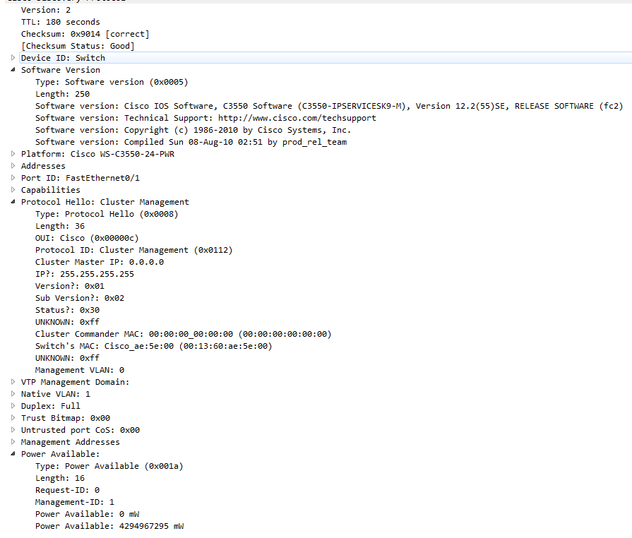
FIgure 1 – Wireshark capture of a CDP Frame
Among many of the fields, some particularly interesting ones for an attacker are: addresses, software version, platform, native VLAN, and management addresses. Capturing all of this information is as easy as opening a Wireshark capture on an interface connected directly to a Cisco device and filtering by CDP (Figure 2).
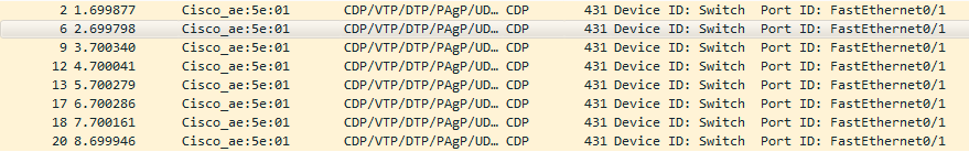
Figure 2 – Wireshark filter of CDP
Because there is no encryption built into the protocol, the best way to mitigate CDP from being used by a malicious party is to just turn it off (Figure 3).

Figure 3 – Turn off CDP globally
An alternative mitigation method would be to leave CDP on globally, but turn it off on interfaces that are not directly connected to another Cisco device (Figure 4). This would allow you to maintain the usefulness of the tool while also mitigating its risk to your infrastructure.

Figure 4 – Turn off CDP on an interface
Virtual Local Area Networks (VLANs)
VLANs separate broadcast domains. Generally, the only way from one VLAN to another is through a router, however, if a switch is misconfigured, you can send traffic from your VLAN to a different VLAN. This is called VLAN hopping. There are two main ways to perform VLAN hopping. An attack can either form a trunk with a switch port or use double tagging.
Forming a trunk
When configuring a switch, there are four different modes you can place a switch in; the table below (Table 1) shows what type of link is formed if a port on one switch (configured with a mode on the left-hand side) is connected to a port of a different switch (configured with a mode on the top).
| Mode 1 | Mode 2 | Mode 2 | Mode 2 | Mode 2 |
|---|---|---|---|---|
| Dynamic Desirable | Dynamic Auto | Trunk | Access | |
| Dynamic Desirable | Trunk | Trunk | Trunk | Access |
| Dynamic Auto | Trunk | Access | Trunk | Access |
| Trunk | Trunk | Trunk | Trunk | Misconfiguration |
| Access | Access | Access | Misconfiguration | Access |
Table 1 – Trunk/Access configurations
By default, all ports on a switch are set to dynamic desirable – this means that it is easy to form a trunk with any port that isn’t explicitly configured. Using a tool called Yersinia, simply launch the GUI with yersinia -G and click the DTP tab. DTP, or Dynamic Trunking Protocol is another proprietary networking protocol developed by Cisco System. It does exactly what the chart above explains. Back in Yersinia, click ‘Launch Attack’ and select ‘enabling trunking’ (Figure 5).
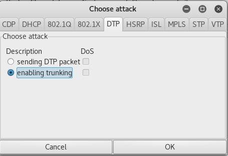
Figure 5 – Enabling Trunking
This negotiates trunking with the switch allowing an attacker to view all network flowing through the trunk. After you’ve formed the trunk, you can send traffic to any VLAN you want by sending it encapsulated in the proper 802.1Q frame. Luckily, Yersinia also has a way for you to send 802.1Q frames! Under 802.1Q, click ‘Launch Attack’ and select ‘sending 802.1Q packet’ (Figure 6).
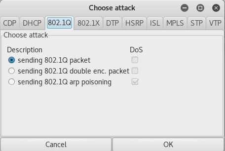
Figure 6 – Sending 802.1Q packet
Double Encapsulation
Another way to perform VLAN hopping is through double encapsulation. In order for this attack to work, the attacker must be placed in the native VLAN. When the frame reaches the first switch, the switch sees that the frame is tagged with the native VLAN. Because the native VLAN is not retagged, the switch strips the native VLAN tag and forwards the frame with the underlying VLAN tag still intact. It’s important to note that this type of attack cannot receive anything back from the target due to the nature of being on a separate VLAN. Figure 7 below outlines the process.
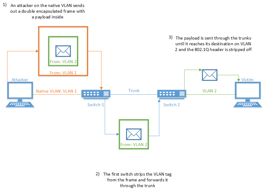
Figure 7 – Double Encapsulation
In order to execute this attack, you must be on the native VLAN. You can determine if you’re on the native VLAN by viewing the CDP frames sent across the network. In Yersinia under the 802.1Q tab, change the value of VLAN to the native VLAN (circled in red in Figure 8) and change the value of VLAN2 to the destination VLAN (circled in blue in Figure 8).
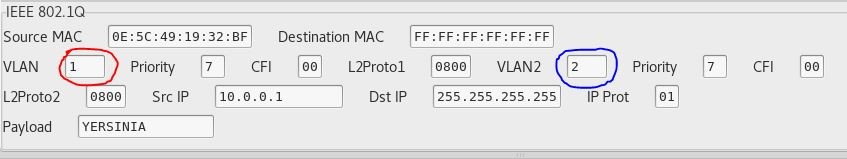
Figure 8 – Changing VLAN numbers
Then, click ‘Launch Attack’ and choose ‘sending 802.1Q double enc. packet’, as seen in Figure 9.
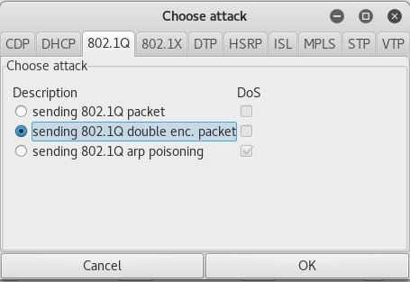
Figure 9 – Launching double encapsulation attack
Mitigations
Preventing VLAN hopping for both double encapsulation and forming a trunk is simple. To prevent a trunk from forming, disable DTP on all ports that are connected to hosts with the interface subcommand switchport mode access and explicitly set all non-trunked ports as access ports with the interface subcommand switchport mode access (Figure 10).
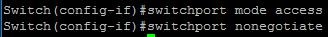
Figure 10 – Disable DTP
To prevent the double encapsulation attack, change the native VLAN to something other than the default (VLAN 1) and do NOT place any hosts on the native VLAN.
Content Addressable Memory (CAM)
The Content Addressable Memory (CAM) is the main differentiator between a hub and a switch. When a frame enters a switch through one of its ports, the switch make a note in the CAM table of the source MAC of the frame and which port it came in on. From then on, whenever a frame has a destination MAC address of the source address it recorded, it doesn’t have to flood the frame out of all of its ports; it only forwards the frame out of the port recorded in the CAM table.
Because switches don’t have an infinite amount of memory, if you push enough MAC addresses into a switch, you will eventually fill up that switch’s CAM table and any new source MAC addresses will not be noted. If the destination MAC address isn’t noted in the CAM table, the switch forwards the frame out of all of its ports, just like a hub. To exploit this, we can use a tool built into Kali Linux called macof. macof floods the local network is random MAC addresses, which in turn overflows the CAM table. Using the setup found in Figure 11, I was able to flood the CAM table, then connect the two clients and view the ICMP traffic that was sent (Figure 12). It’s important to note that this attack only works for new devices. Existing devices will already have a place on the switch’s CAM table and will therefore be unaffected.
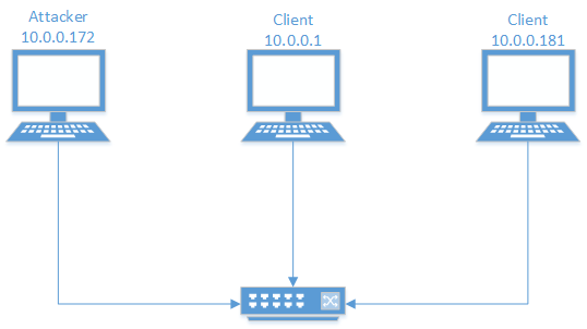
Figure 11 – Setup
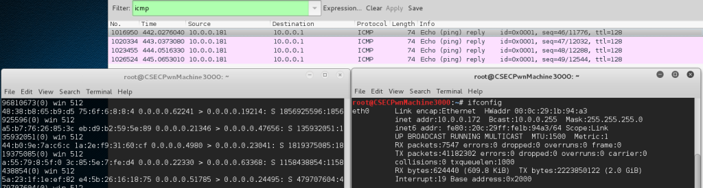
Figure 12 – Results from CAM overflow
One way to protect yourself against such an attack is to enable port-security on the switch. Port-security limits the number of mac addresses on a port to a user-specified amount. The configuration that you want for port-security may vary greatly depending on your needs, so I’ll briefly go over how to configure it. You should configure port-security on all ports that are directly connected to hosts using the interface subcommand switchport port-security mac-address {sticky | <mac-address> [mac-address [mac-address [..]]]} and switchport port-security maximum <max number>. The sticky argument refers to the dynamic list of allowed mac addresses. This means there is no set list of explicitly allowed mac addresses; once the switch sees the first frame on that port, it adds the source mac address to the list of allowed addresses. It continues to do this for all new mac addresses until the size of the list reaches the size specified by the switchport port-security maximum <max number> command. Alternatively, you can specify a list of allowed mac addresses. There are three options for what you want the port to do when a security violation occurs (source 2):
- Protect – drops the frame which caused the violation.
- Restrict – drops the frame which caused the violation and increments the SecurityViolation counter.
- Shutdown – puts the interface in the error-disabled state (effectively shuts the port down) and sends an SNMP trap notification.
You can specify which of these options you want to enforce by using the interface subcommand switchport port-security violation {protect | restrict | shutdown}.
Spanning Tree Protocol (STP)
Spanning Tree Protocol is a data link layer protocol that prevents loops and broadcast storms. In order to prevent loops, switches send out BPDUs (Bridge Protocol Data Units) which contain STP-related information about the switch. Switches first send out BPDUs to determine which switch will be the root bridge. The root bridge is the switch with the lowest bridge ID (bridge ID is the bridge priority + MAC address). From here, the switches determine the local root port which is the port with the least cost to the root. For each switch, it talks with other switches on each network segment it is connected to in order to determine which switch has a lower root cost. The switch with the lowest root cost on that segment then makes the port on that segment the designated port. All other ports in the STP topology are placed in a blocking mode which drops all data received and sends no data. At this point, the spanning tree is complete.
The two big problems with spanning tree that allow us to exploit it lies in a switch’s inherent trust of any BPDU it receives and the time it takes for STP to complete. Because there is no authentication of any BPDU received, anyone could craft and send their own BPDU, disrupting the spanning tree. Additionally, when STP begins, each port on a switch goes through 30 seconds of blocking all user traffic before STP finalizes. This 30 seconds is split up into two sections of 15 sections a piece: the listening section (the switch listens for BPDUs and drops all other traffic) and the learning section (the switch still drops all user traffic but makes note of source addresses on frames to add to the CAM table). For STP, I was unable to get any attacks working, but I will go over the logic of how some attacks work against STP.
Because STP inherently trusts all BPDUs it receives, an attacker could craft their own BPDU claiming to be the root bridge. In order to execute this attack, an attacker would need a computer with two NICs. These two NICs would send BPDUs claiming to be the root switch. In response, the switch the attacker is connected to would send out a topology change notification and STP would begin and end with the attacker as the root switch. This means that the attacker can see all of the traffic that flows through the ‘root switch’.
Another attack an attacker could perform would be to constantly join and leave the spanning tree. Because each topology change takes 30 seconds and blocks all user traffic, an attacker could perform a denial of service attack against a LAN by crafting BPDUs and sending them periodically.
You can mitigate these risks by using the following tools provided on Cisco switches:
- PortFast – this feature, enabled on an interface, skips the listening and learning states in STP and goes directly to the forwarding state. This feature should only be used on ports connected to hosts and should only be used in conjunction with BPDUGuard. Enter spanning-tree portfast in interface configuration mode to enable PortFast
- BPDUGuard – Bridge Protocol Data Unit Guard is used on interfaces with hosts. In essence, if a BPDU is found on that interface, it shuts the interface down. No legitimate user should be generating BPDUs. Enter spanning-tree bpduguard enable in interface configuration mode to enable BPDUGuard.
- Root Guard – Enable root guard between switches that you do not manage. This prevents your switch from learning about a new root through the port root guard is configured on. Enter spanning-tree guard root in interface configuration mode to enable root guard.
Conclusion
While we went over numerous ways to exploit and protect against layer two attacks with Cisco switches, it’s important to note that this blog post is not all inclusive; there are numerous protocols to exploit at the data link layer and various methods to exploit them. The purpose of this blog post is to spread awareness of how easy exploitable the protocols at layer two are and the various ways to mitigate those vulnerabilities on Cisco devices. Hopefully, awareness of these vulnerabilities in layer two protocols will result in future layer two protocols having some built-in security.


Leave a comment